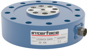
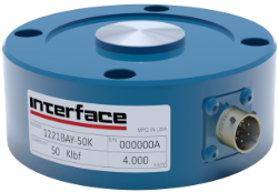
Low profile precision load cell | ±1.5 to ±9000 kN
- High-resistance low profile load cell
- Measuring range: ±5 kN to ± 9000 kN
- Non-linearity: ±0.04%
- Repeatability: ± 0.01%
- Compensation of all transverse efforts
- Low deflection
- Temperature sensitivity < 0.0015% / °C
- Measurement in tension/compression or compression only
- Overload protection: 150% of FSO
- Signal Output : 2 to 4 mV/V depending on the version
- Operating temperature : -55 to 90°C
- optional double or triple bridges
Presentation
High-capacity, high-performance load cells
The 1200 series force transducers meet the most demanding requirements for reliability and performance. Thanks to a design with low sensitivity to transverse loads, this force transducer is particularly well suited to applications, machines and test benches using hydraulic, pneumatic or electric actuators. Measuring ranges are from ±1.5 kN to ±9 MN.
Design
The design of the 1200 series transducers is the result of 50 years of continuous improvement. The choice of gauges, construction, manufacturing and calibration know-how enable us to achieve an accuracy of ± 0.04% of full scale, very high repeatability (< 0.01%) and stability over time (static accuracy: 0.04%). The construction is also virtually insensitive to eccentric (< 0.1% / cm) and transverse (< 0.25%) forces, and very robust, with 150% overload protection.
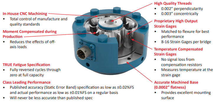
Operating temperature is -55 to 90°C. Calibration is temperature-compensated between -10 and 45°C.
Specifications
- Measurement: tension/compression (12x0) or compression only (12x1, 12x3)
- Bridge power supply: 1-20 VDC
- Bridge resistance: 350 Ohm
- Overload protection: 150%
| Model | Measuring Range | Measurement | Nonlinearity | Hysteresis | Arrow | Output | Weight | Plan |
|---|---|---|---|---|---|---|---|---|
| 1210 | ±1.5 / ±2.5 / ±5 / ±10 kN | T&C | ± 0.04% | ± 0.03% | 0.03 mm | 2.0 mV/V | 0.7 kg | Plan |
| 1210 | ±25 / ±50 kN | T&C | ± 0.04% | ±0.04% | 0.03 mm | 4.0 mV/V | 1.5 kg | Plan |
| 1211 | 0-5 / 0-10 kN | Compression | ± 0.03% | ± 0.03% | 0.03 mm | 2.0 mV/V | 0.7 kg | Plan |
| 1211 | 0-25 / 0-50 kN | Compression | ± 0.04% | ± 0.04% | 0.05 mm | 4.0 mV/V | 1.5 kg | Plan |
| 1220 | ±100 / ±250 kN | T&C | ±0.04% | ±0.04% | 0.05 mm | 4.0 mV/V | 4.3 kg | Plan |
| 1221 | 0-125 / 0-250 kN | Compression | ± 0,05% | ± 0,05% | 0,05 mm | 4,0 mV/V | 3,1 kg | Plan |
| 1231 | 0-450 kN | Compression | ± 0,05% | ± 0,05% | 0,08 mm | 4,0 mV/V | 6 kg | Plan |
| 1232 | ±450 kN | T&C | ±0.04% | ±0.04% | 0.080 mm | 4.0 mV/V | 11.8 kg | Plan |
| 1240 | ±900 kN | T&C | ±0.06% | ±0.06% | 0.30 mm | 4.0 mV/V | 30.9 kg | Plan |
| 1241 | 0-900 kN | Compression | ± 0.05% | ± 0.05% | 0.10 mm | 4.0 mV/V | 18 kg | Plan |
| 1243 | 0-1350 / 0-1800 kN | Compression | ± 0,05% | ± 0,05% | 0,13 mm | 4,0 mV/V | 34 kg | Plan |
| 1244 | ±1200 kN | T&C | ±0.08% | ±0.08% | 0.15 mm | 4.0 mV/V | 31.8 kg | Plan |
| 1252 | ±1800 kN | T&C | ±0.09% | ±0.09% | 0.18 mm | 4.0 mV/V | 45 kg | Plan |
| 1260 | ±2700 kN | T&C | ±0.10% | ±0.10% | 0.2 mm | 4.0 mV/V | 90 kg | Plan |
| 1280 | ±4500 kN | T&C | ±0.15% | ±0.15% | 0.2 mm | 4.0 mV/V | 205 kg | Plan |
| 1290 | ±9000 kN | T&C | ±0.20% | ±0.20% | 0.25 mm | 4.0 mV/V | 390 kg | Plan |
Installation
- Bridge power supply: 1-20 VDC

- Assembly 1: Traction only. Load applied via ball joint + nut. Sensor installation with baseplate, when the installation surface has imperfections (see accessories). Screw types, tightening torques here
- Mounting 2: Compression only. The load is applied to the measuring surface. Sensor installation with baseplate, when the installation surface has imperfections (see accessories). Screw types, tightening torques here
- Mounting 3: tension/compression. The load is applied via a threaded rod + nut. Sensor installed flush with the surface. Screw types, tightening torques here
- Mounting 4: Compression only. The load is applied to the measuring surface. Sensor installed flush with surface. Screw types, tightening torques here
- Mounting 5: Tension/compression, in-line, with baseplate and spherical plain bearings on either side of the transducer. Screw types, tightening torques here
Detailed installation instructions here
Signal conditioning and acquisition
Displays, Amplifiers and Data acquisition modules are offered wherever needed.
Refer also to selection below:
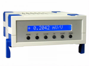
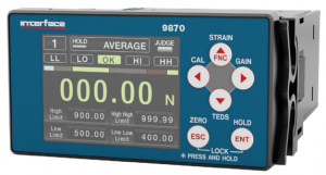
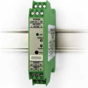
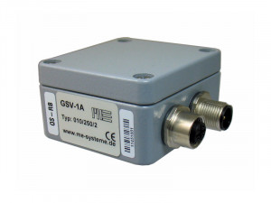
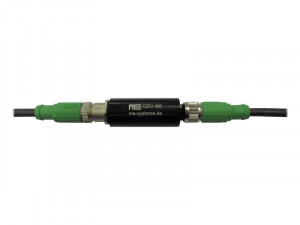
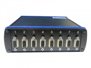
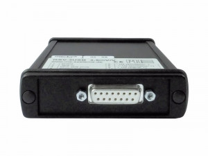
| GSV-2TSDI | 9870 | PMI-520AJ | GSV-1A | GSV-6K | GSV-8DS | GSV-3USB |
|---|---|---|---|---|---|---|
| 24-bit display with acquisition function | High speed indicator | High accuracy analog amplifier, Rail Din | IP66 1-channel amplifier, Voltage or current output | In-line miniature amplifier, voltage / current output | High performance Data acquisition module system | Data acquisition module with USB interface |
 |
 |
 |
 |
 |
 |
 |
Applications
- Aerospace and automotive test benches
- Materials testing
- Test bench instrumentation
- Hydraulic cylinder instrumentation
- Sensor verification
- Calibration benches
Options and accessories
- Type
- pancake
- Precision (max error)
- ≤ 0.1 %
- Nonlinearity (% FS)
- ± 0.04 %
- Hysteresis
- 0.03 % FS
- Nonrepeatability
- 0.01 % FS
- Temperature Compensated Range
- -10 à 45 °C
- Operating temperature range
- -55 à 90 °C
- Zero Balance
- 0.0015 %PE/°C
- Sensibilité du gain
- 0.0015 %/°C
- Analog output signal
- non-amplifié
- Output Signal
- 2 , 4 mV/V
- Résistance du pont
- 350 Ω
- Tension d'alimentation
- 10 Vcc
- Measurement direction
- Traction & Compress.
- Surcharge
- 150 %PE
- Housing
- Steel
- Protection Class
- IP40
- Measuring Range (Force)
- 1 - 100 kN, 100 - 250 kN, > 250 kN, > 1 MN
- Application
- High Accuracy, OEM
-
Datasheet_1200-LC_pmi_FR.pdf
-
Datasheet_1201SCO_pmi_FR.pdf
-
Datasheet_1200HC_pmi_FR.pdf
-
Datasheet_1200HC_pmi_EN.pdf
-
Datasheet_1201SCO_pmi_EN.pdf
-
Datasheet_1200-LC_pmi_EN.pdf
-
1000-1100-1200-3200-Installation.pdf
-
Accessories-Brochure.pdf
-
JN-1.pdf
-
RodEnd-1.pdf
-
TA.pdf
-
1111-and-1211-Drawing.pdf
-
Plan modèle 1221
-
Plan modèle 1231
-
Plan modèle 1241
-
Plan modèle 1243
-
Plan modèle 1220
-
1210-1.5KN-50KN.STEP_.zip
-
1210-1.5KN-50KN-B.STEP_.zip
-
1220-100-250KN.zip
-
1220-100-250KN-B.zip
-
1232-450KN.zip
-
1232-450KN-B.zip
-
1240-900KN.zip
-
1240-900KN-B.zip
-
1244-1200KN.zip
-
1244-1200KN-B.zip
-
1252-1800KN.zip
-
1252-1800KN-B.zip
-
1260-2700KN.zip
-
1260-2700KN-B.zip
-
1280-4.5MN.STEP.zip
-
1280-4.5MN-B.STEP.zip
-
1290-9000KN.zip
-
1290-9.0MN-B.STEP.zip
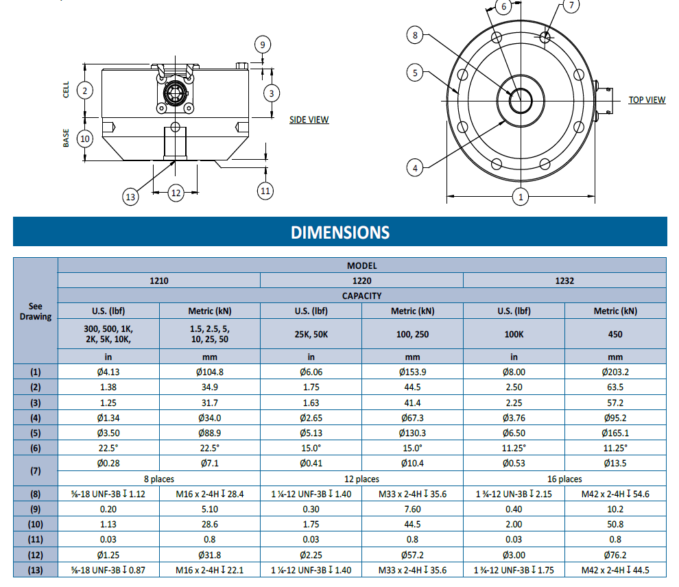
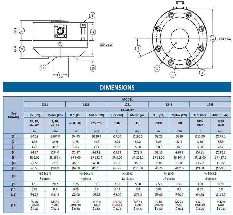
Dimensions 1210, 1220, 1232
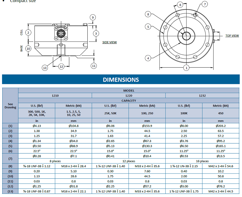
Dimensions 1240, 1244, 1252, 1260, 1280, 1290
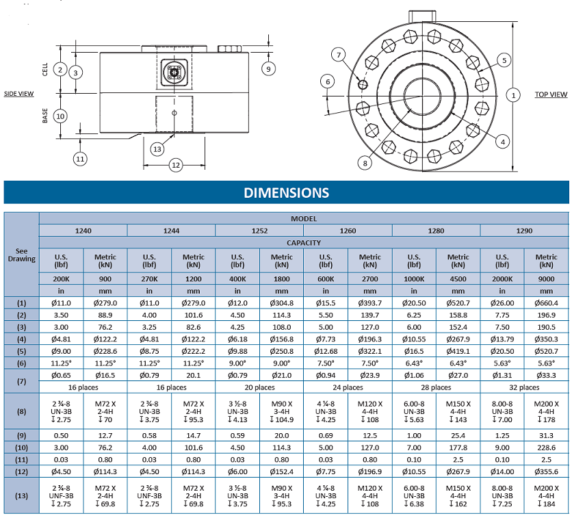
Wiring

Options
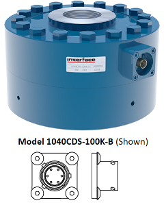
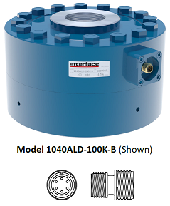
Connectique
| Connecteur Baïonnette | Connecteur vissé | Sortie câble 3m |
|---|---|---|
 |
 |
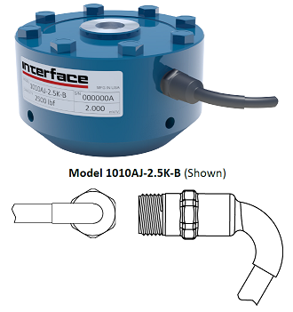 |
| Connecteur PT02E-10-6P / Option ACK ou CDS | Connecteur PC04E-10-6P / Option AF ou ALD | Option AJ |
Pont de jauges redondant
double ou triple
TEDS
selon standard
Calibration
ISO 17025 ou E74 NIST
Base
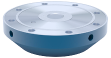
| 1010 | 1010 | 1020 | 1032 | 1040 | 1044 | 1052 | 1060 | 1080 | 1090 |
|---|---|---|---|---|---|---|---|---|---|
| B101(M) | B102(M) | B103(M) | B112(M) | B105(M) | B116(M) | B121(M) | B122(M) | B123(M) | B125(M) |
tige filetée de précision
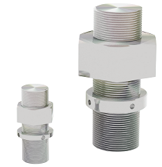
rotules
Montage
| Accessoire | Descriptif |
|---|---|
| Ecrous | --- |
Acquisition
| Accessoire | Photo | Descriptif |
|---|---|---|
| [Afficheur | 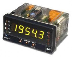 |
Visualisation la mesure en unité , gestion d'alarmes, affichage valeurs max-min |
| Conditionneur |  |
sortie ±5VDC, ± 10 Vcc, 0-10 Vcc ou 4-20 mA. |
| Systèmes d'acquisition | 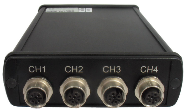 |
Transmission des signaux de mesure vers un PC, un automate programmable, un enregistreur ou une application de supervision type SCADA. Post-traitement des données de mesure via Excel ou Matlab. |
Produits associés
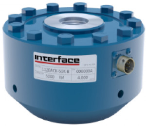
1100 Série - Haute précision

PMI 520 AJ

1000 Série - Fatigue
