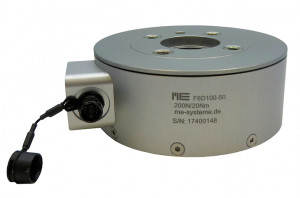
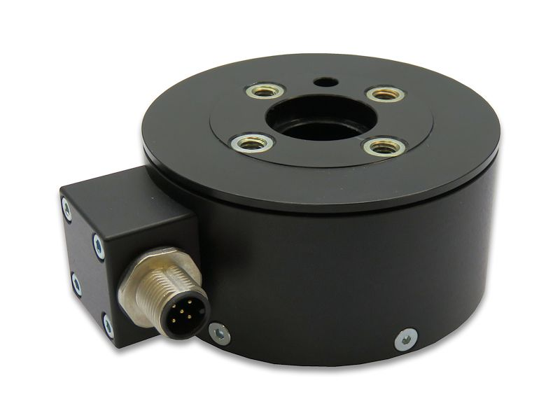
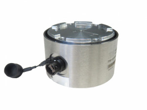
6 axis force/torque transducer - 200 N / 10 Nm to 600N / 30Nm - robotics
- 6-component force/torque transducer of the F6D/K6D series
- Fx/Fy capacity: 100 / 300 N , Fz: 200 / 600 N
- Capacity Mx/My/Mz: 10 / 30 Nm
- For industrial robotic instrumentation according to DIN EN ISO 9409-1
- Accuracy class: 1%;
- Output signal: unamplified (model F6D80-40) or CAN (model F6D80-40e)
- Sampling frequency (F6D80-40e): 12 kHz
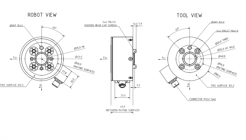
- Dimensions: Ø80 mm x 40 mm;
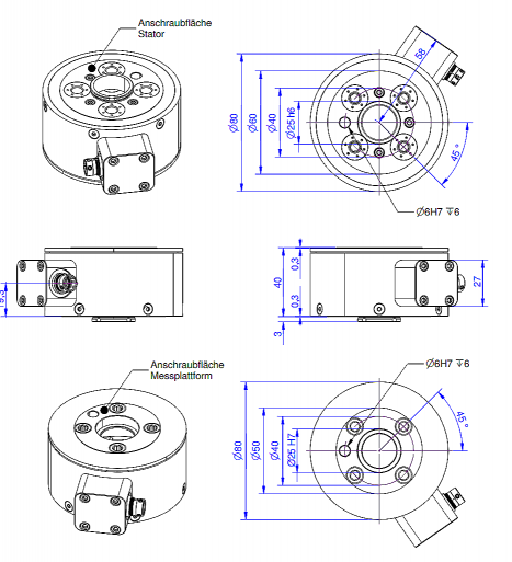
- Mounting: 4 x M6 threads + 1 centering pin Ø6 mm H7
- Connection: MP11 24-pin connector
- IP64 construction in aluminum
- Weight: 320 or 730g
- Calibration certificate and 6x6 channel matrix included
Introduction
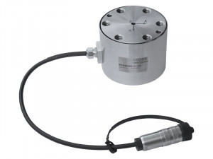
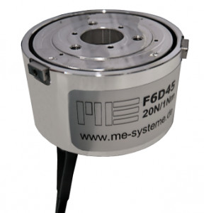
The F6D80-40 and F6D80-40e 6-component force transducers simultaneously measure the forces Fx, Fy, Fz and torques Mx, My, Mz on three perpendicular axes. Each load cell incorporates 6 independent strain gauge force transducers and mounting flanges conforming to DIN ISO 9409-1 for direct mounting on the arm of a robotic manipulator, without additional flanges or adapters. The total space requirement on the robot arm is therefore much smaller than that of the K6D series.
The two sensors F6D80-40 and F6D80-40 are available in two measuring ranges:
- Version 1: Fx/Fy: 100N, Fz: 200N, Mx/My/Mz: 10 Nm
- Version 2: Fx/Fy: 300N, Fz: 600N, Mx/My/Mz: 60 Nm The output signal of the F6D80-40 is a non-amplified analog voltage, while the F6D80-40e has on-board electronics with CAN interface.
The forces are applied on the contour (Ø80-Ø40). The central part is not loaded. The contact surfaces are designed for optimized force transmission, reducing the overall accuracy to 1% (after decoupling), and the sensitivity to transverse forces (crosstalk) to 1%.
Each transducer is delivered with a factory calibration certificate and a 6x6 inter-channel coupling matrix. Calibration to specific ranges is available as an option, as well as ISO-17025 calibration.
Installation
The F6D80-40 and F6D80-40e 6-component force transducers are mounted directly on the robot arm, between the robot and the tool, without any additional flange or adapter.
The introduction of the forces and the fixing to the robot arm are carried out by 4 M6 tappings + 2 centering pins Ø6 mm H7.
The sensor is supplied with a 5 VDC power supply and is delivered with a 12 pin (F6D80-40) or 5 pin (F6D80-40e) MP11 connector. The operating temperature range is -10 to 85°C. The sensor is delivered with a 24-pin connector.
Conditioning, Acquisition, Use of the decoupling matrix
Analog model F6D80-40
The acquisition of the raw measurement signals is done with :
- a PC or PLC acquisition system equipped with a strain gage bridge input card
- or via a conditioning module for strain gage bridge with analog or digital output, then a PC or a standard acquisition system.
The inter-channel decoupling matrix is implemented in the conditioning or acquisition module.
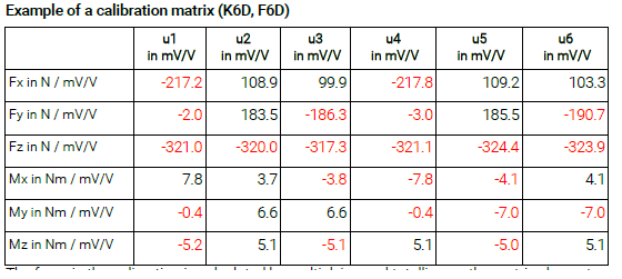
The real forces are obtained by multiplying the 6x6 decoupling matrix (M) by the vector I containing the 6 output signals of the F6D80-40. The origin of the reference frame in which the measured forces are projected is generally the center of the contact surface (see documentation). After neutralization of the inter-channel effects, a force applied on one axis will result in a force variation on only one axis. The accuracy of the measurement is thus improved by a factor of 5 to 10.
PM Instrumentation recommends the GSV series of digital interface conditioning modules for their simplicity of use, their accuracy and their ability to take into account decoupling matrices:
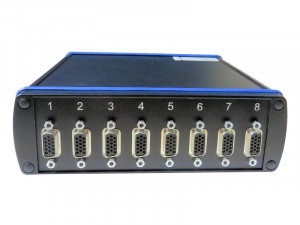
- the GSV-8DS (High performance module, 8 analog inputs) or its ruggedized version GSV-8AS, which can be optionally equipped with a datalogger
- the GSV-6LTE, equipped with a data logger and wireless connectivity
Model F6D80-40e with CAN interface
This model integrates an embedded electronics performing the conditioning of the strain gages, the amplification, the application of the inter-channel matrix, the analog/digital conversion (16-bit) and the CAN interface (proprietary communication protocol)
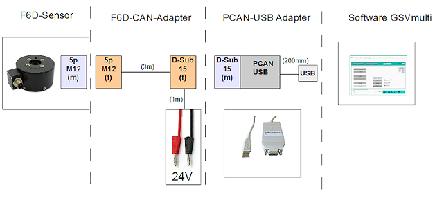
A visualization and acquisition software is included with these modules (GSV-multi). Dll and VI files are also provided for application development under Labview or in C / Visual Studio / C++ / .net.
The use of GSV multi with the CAN interface sensor requires a CAN / USB converter.
Application
The multi-component force sensor is very well suited for use in robotics, e.g.
- For collision detection
- "Teach-In" Collision detection
- Force or torque-controlled operation
Signal conditioning
The force and torque loadings are evaluated e.g. using a GSV-8DS measurement amplifier.
- Type
- 6 axes robotics
- Number of Axis
- 6 Axis
- Precision (max error)
- 1 %
- Nonlinearity (% FS)
- ± 0.1 %
- Hysteresis
- 0.1 % FS
- Operating temperature range
- -10 à 85 °C
- Analog output signal
- non-amplifié
- Output Signal
- 0.4 mV/V
- Tension d'alimentation
- 5 Vcc
- Measurement direction
- Traction & Compress.
- Housing
- Aluminium
- Protection Class
- IP64
- Measuring Range (Force)
- ⩽ 1 kN
- Application
- OEM, Robotics
- Calibration custom, ISO-17025
- Cable and connection for GSV
- Temperature compensated calibration
- TEDS

