Accuracy of multi-component sensors
Definition of accuracy and crosstalk
In order to define the accuracy of a multidimensional sensor, firstly two important terms should be distinguished: the sensor accuracy and the crosstalk.
The term "accuracy class", which appears in all data sheets and product descriptions, refers to the accuracy of the sensor.
In the document sensors: accuracy, there is a detailed explanation of this term and a summary of the most important criteria for the accuracy class:
For force and torque sensors, the following properties are used for classification into an accuracy class:
- relative standard uncertainty
- relative deviation of linearity and hysteresis
- temperature drift of the zero signal
- temperature drift of the slope of the curve
In the multi-axis and multi-component sensors occurs another effect, the so-called crosstalk. Here is an explanation from the document multi-component sensors:
Crosstalk
The force or torque introduction into the measuring axis also results in an indication in the thereto perpendicular axes. This effect is referred to as crosstalk.
For three-axis force sensors and multi-component force sensors, the crosstalk when effects the nominal load is approx. 1% of the nominal load of the other axes.
Crosstalk is proportional to the amount of load. With increasing levers or larger moments the deformation of the sensor and the crosstalk is increasing.
The calibration takes place at the level of the front face of the sensor. In this level is also the origin of the multi-axis force sensor. In the actual application the fore application point (operating point) is usually not located in the origin of the multi-axis force sensor. This creates additional torques.
These additional torques must be considered during the selection of the measuring range to prevent overloading of the sensor.
If the torques should be calculated at the force application point, so is an additional arithmetic operation or alternatively a transformation of the calibration matrix necessary. The operation is described in the instructions ba-k6d.pdf. The software GSVmulti allows the input of the distance of the force application point from the coordinates origin.
The crosstalk in every operating point can be minimized via calibration in this point. The additional torques are taken into account during the calibration in the operating point and included in the error compensation.
Methods of calibration
Calibration for special load vectors
The special option "Matrix Plus" allows the reduction of crosstalk in the operating point up to 0.2% or 0.5%. This option "Matrix Plus" includes:
a quadratic approach to compensate errors and/or a calibration in the operating point of the planned application of the sensor or a calibration with the load vector of the intended application in the origin of the sensor. The quadratic approach of the error compensation minimizes the crosstalk exactly in the operating point. At higher loads, the quadratic approach can lead to larger errors than error compensation with a linear approach.
The calibration with the load vector of the intended application also minimizes crosstalk for this load vector.
The selection of the respective procedure depends on the availability of calibration accessories and the individual requirements of your application.
Universal Calibration
A calibration with 100% nominal load is recommended for applications where the load vector is unknown. In order to minimize the crosstalk, an additional quadratic approach "matrix plus" may be applied with a mathematical optimization for the load cases 20%, 40%, 60% and 80% of the nominal load.
The value of the crosstalk is specified in each datasheet by multi axis and multi-component sensors separately from the accuracy class.
Summary
Accuracy and crosstalk are reported separately for 6-axis (force/torque) sensors. The accuracy class is typically given as 0.2%, the crosstalk as 1%. As a rule, the temperature-induced drift of 6-axis sensors leads to a reduction of the accuracy class to 0.2%. Reproducibility (standard uncertainty) and linearity are on the order of 1-axis force sensors with accuracy class 0.1%.
The special calibration methods minimize the crosstalk to the range of 0.2%...0.5%.
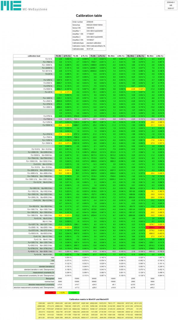
Examples of the accuracy of K6D sensors
| K6D80 2kN/100Nm | Calibration with 100% nominal load; Standard calibration, "K6D-Calibration-Matrix" |
|---|---|
| K6D40 200N/5Nm | Calibration with partial load 5% and 0.1%. Standard calibration, "K6D-Calibration-Matrix" |
| K6D40 200N/5Nm | Calibration with partial load 5% and 0.1%. Calibration with partial loads, "Matrix-Plus" |
| K6D68 10kN/50Nm | Calibration with 100% nominal load; Standard calibration, "K6D-Calibration-Matrix" |
| K6D68 10kN/50Nm | Calibration with 100% nominal load; Standard calibration, "Matrix-Plus" |

